GearInPos (Flying Saw)
See the BasicMotion_GearInPos.project example in the installation directory of CODESYS under ..\CODESYS SoftMotion\Examples.
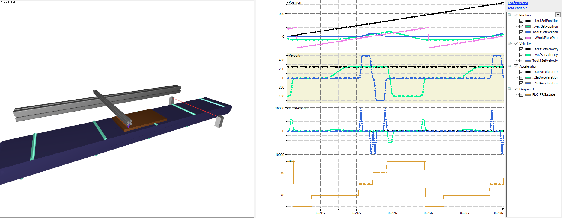
This example shows how to use MC_GearInPos to implement a flying saw. For this project, we recommend installing CODESYS Depictor, which can display the application as a 3D animation. (The unlicensed free version is enough to do this.)
Structure of the application
The application consists of a state machine in the PLC_PRG program, a 3D representation (Scene, DepictorCalculation program), a simple workpiece simulation (SimulateWorkpiece program), and a trace which you can use to easily comprehend the effect of the function blocks.
The flow in PLC_PRG is as follows:
Enable the axes with
MC_Power. (STATE_POWER)Wait until the light barrier detects a workpiece. (
STATE_WAIT_FOR_WORKPIECE)As soon as the light barrier detects a workpiece, the slave which transports the saw parallel to the conveyor belt is synchronized with the workpiece on the conveyor belt (controlled by the
Masteraxis). (STATE_WAIT_FOR_SYNC)When synchronization is reached, the saw is moved forwards and backwards once perpendicularly to the workpiece. (
STATE_MOVE_TOOL_0/1)Move the slave to the rest position and start the process again at 2. (
STATE_MOVE_TO_REST)
Coordinate systems and dimensions
The origin of the coordinate system is at the center of the conveyor belt, the Z-axis points upwards, and the X-axis points in the direction of movement of the conveyor belt. From the conveyor belt, the Y-axis points away from the saw.
The dimensions of the conveyor belt and workpiece, the position of the light barrier, and the position where the saw runs synchronously with the workpiece are stored as constants in the GVL Const.
Usage
Start the application. In the Scene Depictor object and in the trace, you can see how the synchronization between the master (workpiece on the conveyor belt) and the slave (saw) is performed.